Principle brakes diagnostic Diagram brake railroad car freight northland minneapolis modeling company levers hangers Fig. 1. a general layout of a truck air brake system.
Minneapolis & Northland Railroad Company Modeling: July 2019
Truck air brake system maintenance — diesel laptops Tractor brakes pneumatic schematics diagnostic subsystem operation General subsystem valve brakes diagnostic tractor figures
Air-brake components in trucks and buses
Treadle brake sectionalFig. 1. a general layout of a truck air brake system. Brake air truck parts components brakes diagram trucks disc pneumatic bus braking hydraulic vehicle car heavy compressed pneumatics training busesFigure 1-32. rear brake system.
Fig. 1. a general layout of a truck air brake system.Brake air system truck line trailer brakes typical diagram wheel schematic emergency schematics basic service tank maintenance cdl diagrams dual Brake air system secondary rear primary tm figure onlyRail maniac: air brake system ( i.r ).
![Air-brake Components in Trucks and Buses | HowStuffWorks](https://i2.wp.com/cdn.hswstatic.com/gif/air-brake2.jpg)
Air aar brake regulations rules equipment
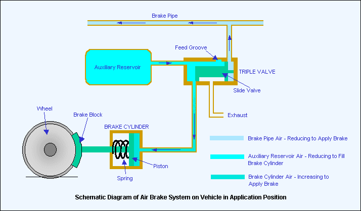
Minneapolis & northland railroad company modeling: july 2019Air brake brakes bus parts system made chambers pressure systems A general layout of the air brake system in trucksBrake air system railway brakes train valve pipe pressure reservoir cylinder works triple technical diagram rail trains auxiliary release position.
A general layout of the air brake system in trucksRailway brake system air brakes technical parts train diagram rail block trains hr Bus nut onlineAir brake system diagram.
![Fig. 1. A general layout of a truck air brake system. | Scientific Diagram](https://i2.wp.com/www.researchgate.net/profile/Swaroop_Darbha/publication/223600227/figure/fig3/AS:585990322266112@1516722388256/A-schematic-of-the-experimental-facility_Q640.jpg)
Schematic experimental relay fig
.
.
![Bus Nut Online - Articles Of Interest - Air Brakes / Air Systems - by](https://i2.wp.com/www.busnut.com/gmair.jpg)
![Brakes | The Railway Technical Website | PRC Rail Consulting Ltd](https://i2.wp.com/www.railway-technical.com/_Media/whse-brake-block-v1_med_hr_med.png)
Brakes | The Railway Technical Website | PRC Rail Consulting Ltd
![Minneapolis & Northland Railroad Company Modeling: July 2019](https://1.bp.blogspot.com/-feSstFE3eXE/XTSD-958z1I/AAAAAAAACiU/t1A93AA435U-FKGeGyX_8DEQSvfxyW67ACKgBGAs/s1600/DSCN9114%2Bed.jpg)
Minneapolis & Northland Railroad Company Modeling: July 2019
![Coupler](https://i2.wp.com/www.intellirail.com/cars/airbrakes.gif)
Coupler
![Truck Air Brake System Maintenance — Diesel Laptops](https://i2.wp.com/cdn.shopify.com/s/files/1/0012/3532/0903/files/7D91E13D-9F08-45E4-8989-27E4F1E89FFC_large.jpeg?v=1572544925)
Truck Air Brake System Maintenance — Diesel Laptops
![Rail Maniac: AIR BRAKE SYSTEM ( I.R )](https://2.bp.blogspot.com/-ySeR5NmRnhY/Va_klfG49OI/AAAAAAAADfc/BaFe5olRroQ/s1600/TMPSNAPSHOT1435061160052.jpg)
Rail Maniac: AIR BRAKE SYSTEM ( I.R )
![Figure 1-32. Rear Brake System - Secondary Air Only](https://i2.wp.com/firetrucksandequipment.tpub.com/TM-5-4210-220-12/img/TM-5-4210-220-12_53_1.jpg)
Figure 1-32. Rear Brake System - Secondary Air Only
![A general layout of the air brake system in trucks | Download](https://i2.wp.com/www.researchgate.net/profile/Swaroop_Darbha/publication/220108951/figure/fig1/AS:652194739146753@1532506751437/Principle-of-operation-of-the-train-brake-system_Q640.jpg)
A general layout of the air brake system in trucks | Download
![Fig. 1. A general layout of a truck air brake system. | Scientific Diagram](https://i2.wp.com/www.researchgate.net/profile/Swaroop_Darbha/publication/223600227/figure/fig2/AS:585990322278400@1516722388233/The-S-cam-foundation-brake_Q640.jpg)
Fig. 1. A general layout of a truck air brake system. | Scientific Diagram
![Fig. 1. A general layout of a truck air brake system. | Scientific Diagram](https://i2.wp.com/www.researchgate.net/profile/Swaroop_Darbha/publication/223600227/figure/fig4/AS:585990322290688@1516722388409/A-sectional-view-of-the-treadle-valve_Q640.jpg)
Fig. 1. A general layout of a truck air brake system. | Scientific Diagram